Understanding the Attitude Indicator Diagram – A Comprehensive Guide
What is an Attitude Indicator?
The attitude indicator (AI), also known as the artificial horizon, ranks among aviation’s most essential flight instruments—a device that reveals an aircraft’s orientation relative to Earth’s horizon. Among the six basic flight instruments, it provides an immediate, intuitive picture of the aircraft’s position in three-dimensional space.
This instrument measures two fundamental aspects of flight: pitch (whether the nose points up or down) and bank (how the wings tilt left or right). With this single display, pilots can instantly determine if they’re climbing, descending, or turning—all without relying on external visual cues.
The indicator becomes invaluable by revealing the aircraft’s spatial orientation across both pitch and roll axes. It proves most valuable during high-speed maneuvers or when visibility vanishes—whether shrouded in clouds, flying through night’s darkness, or navigating other conditions where the natural horizon disappears.
The AI’s key advantage lies in its intuitive design. Unlike instruments demanding careful interpretation, its pictorial display allows pilots to make quick, instinctive control decisions. Even subtle orientation shifts register immediately, making it crucial for maintaining stable flight—particularly when flying solely by instruments.
Components of the Attitude Indicator Diagram
Every attitude indicator contains a precision gyroscope, surrounded by several critical components that work together. This gyroscope maintains rigidity in space, establishing an unwavering reference point for all orientation measurements.
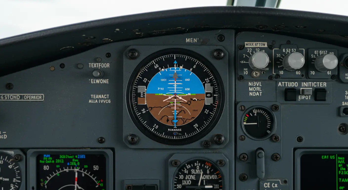
A miniature aircraft symbol sits fixed on the instrument face, serving as your aircraft’s representative in this miniature world.
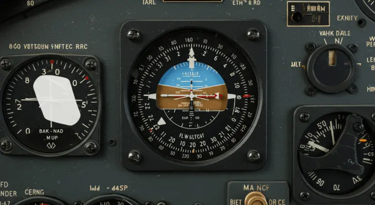
The artificial horizon line creates a vivid division across the instrument face: blue above (sky) and brown or black below (ground). This horizon line moves with your aircraft’s movements—pitching up sends the line downward on the display, while banking causes it to rotate accordingly. This creates an instant visual representation of the aircraft’s position.
Precision comes through pitch and roll scales marked with degree measurements. These allow pilots to maintain exact attitudes during complex maneuvers.
How the Attitude Indicator Works
The attitude indicator operates through gyroscopic rigidity. A high-speed gyroscope, cradled within a double gimbals system, maintains its spatial orientation regardless of how dramatically the aircraft moves around it.
The physics work as follows: as the aircraft changes orientation, the gyro remains steadfast in space while the instrument case follows the aircraft’s every movement. This relative motion transforms into the visual information displayed on the instrument face. Connected to a graduated card, the gyro reveals precise pitch and bank measurements—showing the aircraft’s exact position relative to the horizon.
Traditional indicators often rely on vacuum power, while modern glass cockpits use electronic systems. Today’s advanced electronic systems—including the Attitude Heading Reference System (AIRS), Inertial Reference Unit (IRU), and Inertial Navigation System (INS)—provide data for sophisticated electronic displays.
The attitude indicator reveals both bank (wing angle relative to horizon) and pitch (nose angle to horizon). This distinguishes it from the turn coordinator, which focuses solely on turn rate.
Different aircraft types handle attitude indication. In smaller aircraft, the indicator mirrors the aircraft’s movement—bank left, and the indicator leans left with you. Commercial aircraft flip this relationship: a left bank tilts the indicator right. These different approaches show different approaches to instrument presentation across aviation’s diverse aircraft categories.
A self-erecting mechanism helps maintain gyroscopic accuracy, automatically correcting minor drift during flight. However, pilots must remain vigilant—rapid acceleration or deceleration can introduce temporary pitch errors that require awareness and compensation.
Understanding Aircraft Orientation
Common Errors and Limitations of Attitude Indicators
Even reliable attitude indicators face inherent limitations and potential errors:
Smart pilots counter these limitations through cross-checking with other flight instruments and maintaining rigorous system maintenance schedules. This practice is especially important when flying in instrument meteorological conditions.
The Role of Flight Director Attitude Indicators
Flight Director Attitude Indicators (Dais) offer significant advances in aircraft instrumentation, combining traditional attitude indication with sophisticated guidance capabilities. These advanced systems provide advanced navigation capabilities in both cutting-edge aircraft and spacecraft operations, offering precise orientation data alongside intelligent flight path guidance.
In spacecraft applications, the FDI displays three-dimensional space, displaying yaw, pitch, roll, and orbital position data from an Inertial Measurement Unit (IMU). The system offers configurable reference points—whether Earth-based or celestial—providing the precision necessary for complex maneuvers like orbital docking.
Aviation knows these systems as Attitude Direction Indicators (ADI’s). They work with Flight Director Systems (FDS), overlaying command bars (or V-bars) that show the computed optimal flight path.
The pilot’s task is straightforward: follow the command bars. By maneuvering the aircraft to align its symbol with these bars, precise pitch and bank adjustments happen naturally.
Combining attitude information with flight path guidance significantly reduces pilot workload. Whether executing precision instrument approaches, navigating complex departure procedures, or battling challenging weather, these systems perform well. By consolidating critical flight information into one intuitive display, flight director attitude indicators allow precise aircraft control while enhancing situational awareness—an important safety advancement in modern aviation.
Visual Representation of the Attitude Indicator
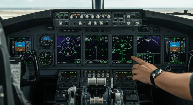
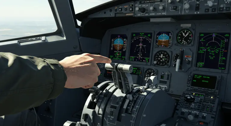
Modern glass cockpits integrate the attitude indicator into Electronic Flight Instrument Systems (ELIS), preserving the fundamental visual concept while adding sophisticated enhancements. These digital displays often feature dynamic color-coding, adaptive scaling, and integrated vertical speed data—continuous improvement.